Question 4
Fig. 2 shows the sketch plan of a twin 2 bedroom bungalow. Study he given specifications and answer the questions that follow.
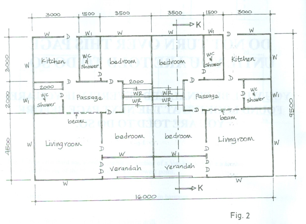
SPECIFICATIONS
All dimensions are given in millimetres.
FOUDATION: 675 x 225 concrete strip foundation on 15 blinding at1000 from ground level.
FLOOR: 250 hardcore, 150 concrete, 225 terazzo floor finish;
Floor level is 150 above the ground level;
Floor to ceiling 3100.
WALLS: All walls 225 with 13 mortar rendering on both sides.
DOORS: D - 2100 x 900 x 38 flush in 150 x 50 timber frame;
DD - 2100 x 1200 x 25 glazed metal door.
WINDOWS: All casement glazed in metal frame;
W1 – 900 x 600;
W – 1800 x 1200.
WARDROBES: WR – 2100 x 2000 wooden with sliding doors.
BEAM/LINTEL: 225 X 225 reinforced concrete at 210 above floor level;
Beams are located at entrances into verandah and passage.
VERANDAH: 75 cylindrical hollow aluminium pipe fixed at 50 above 1000 high dwarf wall.
ROOF: 25 bituminous felt roof finish;
150 reinforced concrete slab;
300 x 300 x 75 parallel concrete coping placed on 1100 high parapet
wall;
25 deep roof gutter;
Eaves projection 900.
(a) Draw to a scale of 1: 100, the:
(i) floor plan;
(ii) front elevation.
(b) Draw to a scale of 1:50, the sectional view on plane K – K.
Observation
Most of the candidates attempted this question and they performed well.
Candidates are expected to do the following:
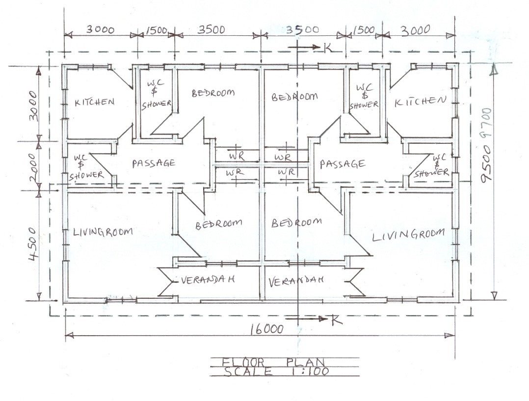
FLOOR PLAN
(i) draw to correct scale (1:100) ;
(ii) draw the walls;
(iii) draw the beams;
(iv) draw the windows;
(v) draw the doors;
(vi) draw the ridge cap;
(vii) draw the cutting plane k-k;
(viii) draw the eaves projection;
(ix) draw the wardrobes;
(x) label the spaces;
(xi) write floor plan.
The solution is shown below:
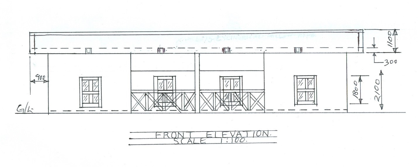
FRONT ELEVATION
(i) draw to correct scale;
(ii) draw and indicate ground line
(iii) draw the floor level;
(iv) draw casement windows with convention;
(v) draw the column;
(vi) draw two beams;
(vii) draw all the walls;
(viii) draw the parapet roof ;
(ix) draw 75mm cylindrical hollow aluminum pipe;
(x) draw the eaves;
(xi) write front elevation
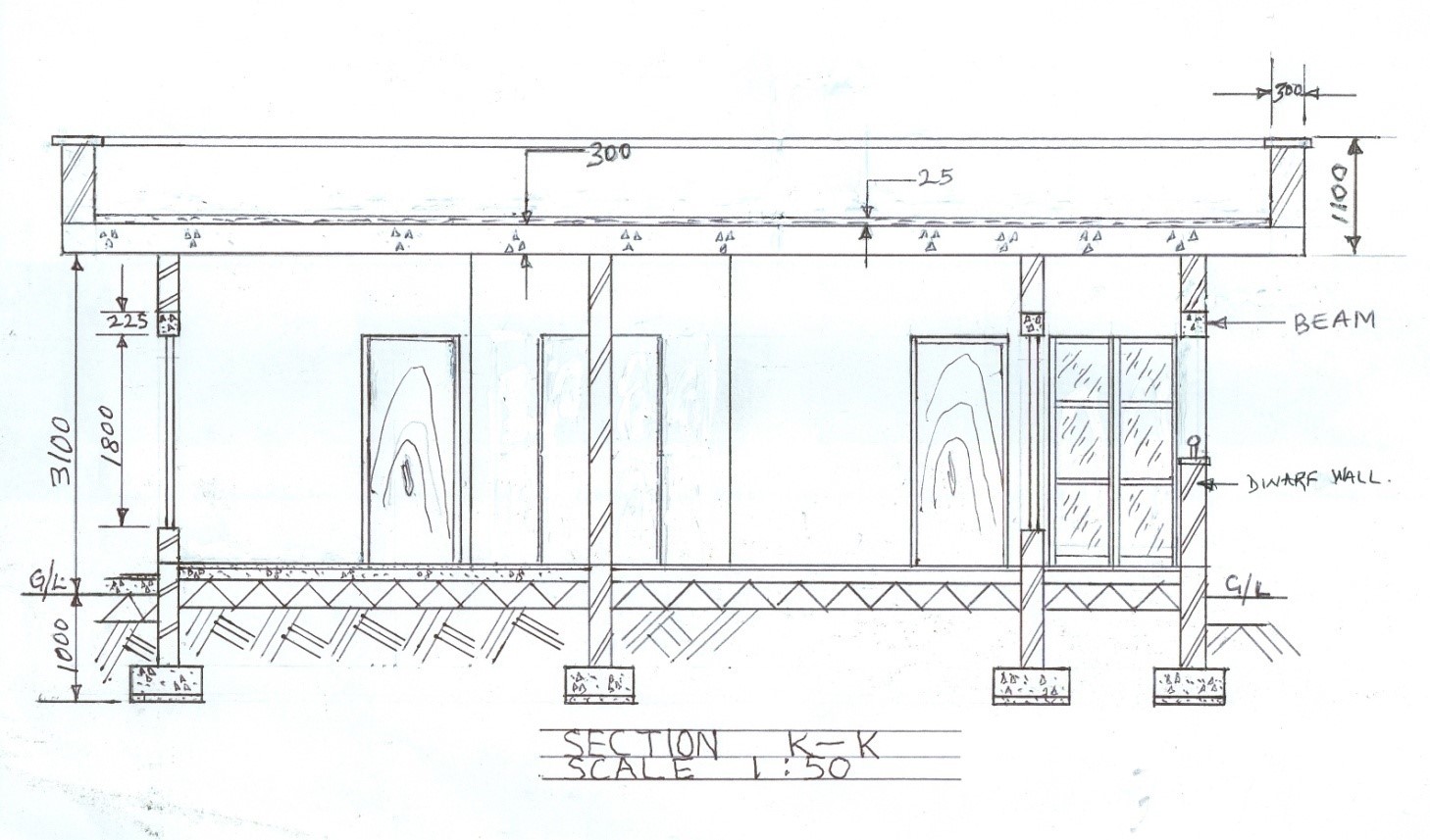
SECTIONAL VIEW K- K
(i) draw to correct scale;
(ii) draw the ground line;
(iii) draw 4 foundation footings with convention;
(iv) draw the earth core with convention;
(v) draw the hardcore with convention;
(vi) draw the concrete slab with convention;
(vii) draw the floor finish;
(viii) draw the 4 walls in elevation draw;
(ix) draw two lintels;
(x) draw one beam;
(xi) draw two flush and casement doors in elevation;
(xii) draw two windows in section;
(xiii) draw two wardrobes with sliding doors in elevation
(xiv) draw the parapet roof;
(xvi) show four important dimensions ;
(xvii) write sectional view K-K;
(xviii) draw neatly.
The solution is shown below: