Question 4
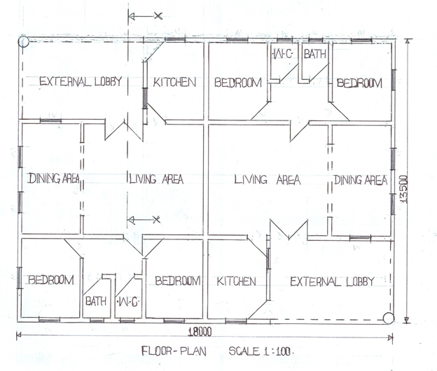
The figure below shows the sketch plan of a bungalow. Study the given specifications and use them to answer the questions that follow.
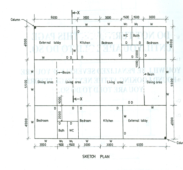
SPECIFICATIONS
All dimensions are given millimeters.
FOUNDATION: 150 x 450 concrete strip on 15 blinding at a depth of 1000 below the ground
Level;
FLOOR: 150 hardcore; 150 concrete slab;
12 mortar screed floor finish;
Dining area floor level is 150 higher than that of the living area
General floor level to ceiling 3150.
WALLS: All walls 150 with 12 mortar rendering on both sides.
LINTEL: 225 x 150 reinforced concrete.
BEAM: 225 x 150 reinforced concrete at 220 above living area floor level.
COLUMN: 225 diameter, reinforced concrete with extended circular base and top.
DOORS: D-flush, 2100 x 900 x 38 in 150 x 50 timber frame.
WINDOWS: W1 – 700 x 700 top hung aluminium casement.
W – 1000 x 1200 glass louvred in 100 x 50 timber frame.
ROOF: 150 reinforced concrete with 25 bituminous felt roof finish.
Eaves 800.
Note: The roof covers the two external lobbies.
EXTERNAL LOBBY: Open, without balustrades and ground level and at 150 below the general
floor level.
- Draw, to a scale of 1 : 100, the:
(i) floor plan;
(ii)front elevation.
(iii)Draw to a scale of 1:50, a sectional view on X – X. Indicate any 4 specifications on the section.
[Assume suitable dimensions where necessary]
Observation
Candidates were asked to draw the floor plan, front elevation and sectional view on plane X – X. Most of the candidates attempted this question and their performance was okay. However, some of the candidates could not draw correctly the specified roof in both the front elevation and the sectional view.
Candidates were expected to do the following:v
FLOOR PLAN
(i) draw to scale 1:100 (18,000 x 13,500 ± 10);
(ii) draw the walls;
(iii) draw the cutting plane X – X;
(iv) draw the windows (20 in number);
(v) draw the doors (18 in number);
(vi) draw the beams (6 in number);
(vii) draw the columns (2 in number);
(viii) label the partitions (16 in number);
(ix) write floor plan and scale;
(x) draw neatly.
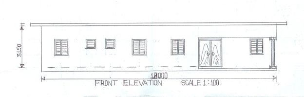
FRONT ELEVATION
(i) draw to scale 1:100 (18,000 x 13,500 ± 10);
(ii) draw the ground;
(iii) draw the finished line;
(iv) draw the living room floor line;
(v) draw the four vertical lines;
(vi) draw the beams (horizontal line);
(vii) draw the columns with circular base and top;
(viii) draw six conventional windows;
(ix) draw the double door;
(x) draw the concrete roof;
(xi) draw the eaves projection;
(xii) write front elevation and scale;
(xiii) draw neatly.
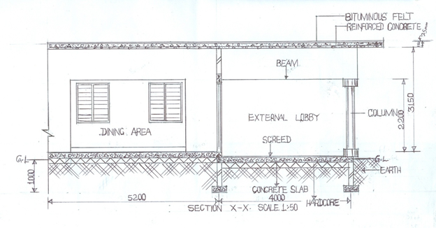
SECTIONAL VIEW ON X – X
(i) draw to scale 1:100 (18,000 x 13,500 ± 10);
(ii) draw two foundation footings;
(iii) draw earth filling, hardcore, concrete slab and the screed;
(iv) draw the ground line from the base of the foundation;
(v) draw the cut edge;
(vi) draw two walls in section;
(vii) draw two walls in elevation;
(viii) draw the finished floor in dining area;
(ix) draw beams (two in number);
(x) draw one door in section;
(xi) draw one lintel;
- draw one column with circular base and top;
- draw two windows in elevation;
- draw reinforced concrete;
- draw roof cover (bituminous felt);
- indicate four specifications;
(xvii) write section x – x and scale;
- draw neatly.
The solutions are shown below: