
Question 2
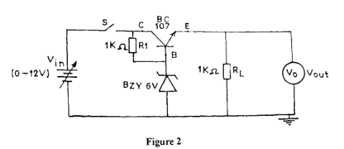
- Connect the circuit diagram as shown in Figure 2.
- Ask the supervisor to check the circuit connection.
- You are provided with Table 2.
Table 2
Vin (V) |
Vout (V) |
2 |
|
4 |
|
6 |
|
8 |
|
10 |
|
12 |
|
- Set the power supply unit to 2 V.
- Close switch (S).
- Read and record in Table 2, the value of Vout (V).
- Open switch (S).
- Repeat steps (d) to (g) for the other values of Vin (V) in Table 2.
- On the same graph sheet used in Question 1, plot a graph of Vout (V) on the vertical axis and Vin (V) on the horizontal axis using Table 2.
- From your graph:
(i) determine the zener voltage for the Zener diode;
(ii) state the effect of the Zener diode on the output of the circuit.
Observation
The expected responses were:
Table 2
Vin (V) |
Vout (V) |
2 |
1.0 - 2.0 |
4 |
3.0 - 4.0 |
6 |
5.0 - 6.0 |
8 |
5.0 - 6.0 |
10 |
5.0 - 6.0 |
12 |
5.0 - 6.0 |
(i) A graph with origin (0, 0) containing both two linear segments and a non-linear segment showing features such as title, labelled axes, appropriate scales, correct point picking and line of best fit.
(j)
(i) Zener voltage = 5.0 V to 6.0 V (or as deduced from candidates’ graph)
(ii) The output remains constant at (5.0 V - 6.0 V) when the input is greater than
(5.0 V– 6.0 V)
Both questions required candidates to connect circuit, measure and record readings of output voltage Vout (V) as input voltage Vin (V) is varied, thereafter, use the values obtained to plot a linear and a non-linear curve the same graph sheet. The Chief Examiner reported that though majority of the candidates obtained reasonable readings, very many of them were unable plot graphs as expected.