
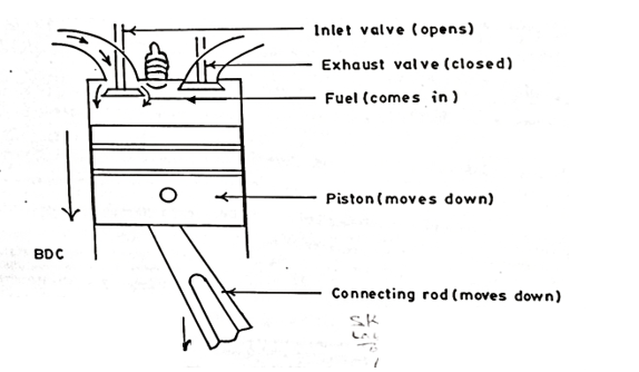
(2) (a) Sketch to show the induction stroke of a four-stroke petrol engine indicating
the positions of piston, valves and the connecting rod.
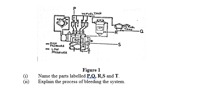
(b) The sketch in Figure 1 shows the fuel supply system of a compression ignition engine.
Candidates’ responses to questions were not adequate. They found it difficult to sketch the engine stroke and name the labelled parts of the fuel system. The solutions to the poorly answered question are given below.
(a)Sketch to show induction stroke
P: Injector
Q: Fuel lift pump
R: Fuel filter
S: Injector pump, fuel injector pump
T: Bleeding nipple
(ii) Process of bleeding the system
- Ensure there is enough fuel in the tank.
- Slacken the bleed nipple or bleed screw.
- Operate the priming lever and observe the fuel flow until there is no air bubble.
- Finally, lock the bleed nipple or screw.